|
In software, a stack is datastructure which supports three operations:
push, pop and top. In this assignment, you are
going to design a simple stack in hardware.
For simplicity, the data elements that are going to be stored in the stack
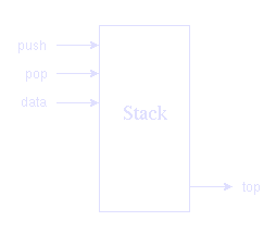
are booleans (or, if you want, bits). The stack is implemented as a stateful circuit with three inputs, called
push, pop, and data, and one output, called
top.

The behaviour of the stack is as follows. If push is high, then the
data element is pushed on the stack. If pop is high, then
the top of the stack is taken away, and the data input is ignored.
If neither push nor pop is high, nothing happens.
At all times, the output top reflects the value of the top of the
stack, so no special request to see the top of the stack is required.
It is unspecified what happens when push and pop are
high at the same time, when the stack is empty and pop is high, and
when the stack is full and push is high.
Exercises
|
a. Design a stack which can store at least 4 data elements. Again, you may use block diagrams,
textual notation, or any other description method you are familiar with.
Hint: a possible stack design consists of four identical
cells, each
cell corresponding to a place in the stack. Cells keep track of the data
stored in them and whether they are at the top of the stack or not.
b. Add two extra outputs, called empty and full, which
are high if the stack is respectively empty or full.
c. Add one extra output, called error, which becomes high if
something has gone wrong.
d. (*) What invariants hold for the delay elements in your design? (An
invariant is a property which is true at all times).
|
|

